
1. HI-FI Amplifier Requirements
Amplifier definition
In theory the perfect amplifier is the one who reproduce at output exactly the same shape of signal applied to the input but amplified (scaled up) with a factor A named Amplification.
In practice the amplified output signal has some modifications compared to input, named distortions.
Audio amplifier
An AUDIO amplifier is an amplifier designed to amplify those signals that are audible by humans.
Depending of its goal an audio amplifier can amplify just a part of the audible signals, or all of them.
HI-FI audio amplifier
To qualify as an HI-FI amplifier it must:
- cover full band of audible frequencies, considered to be between 20Hz and 20000Hz
- have the capacity to reproduce input signales at output with a very high grade of accuracy (less distortions).
What to expect and how to test a HI-FI amplifier
Basic theory
First let's consider 20000Hz the upper limit of audible frequencies. This is a convention because each of us has a different audible acuity, usually the upper heard frequency by different humans is much lower, about 12000-16000Hz.
Second, remember that Fourier demonstrated that any repetitive signal of any shape can be decomposed in a sum of sinusoids, each having a different amplitude and frequency.
Third, an audible signal of any shape decomposed, is a sum of audible frequency sinusoids.
Forth, remember that the goal of an high fidelity amplifier is to amplify(magnify) the input audio signal, without distortions (modifications of signal shape).
The most usual distortion
Now consider that a pure sinusoid of 1000Hz is applied at the amp input. We expect to have a 1000Hz pure sinusoid of bigger amplitude at the output. But what happen when the volume is increased over the limit of clipping (the output signal tends to exceed the values of power supplied to amplifier)? The output signal will be a flat top and bottom sinusoid which is a different shape signal than the input. This altered signal is not a pure sinusoid so it will be a sum of sinusoids. Practically it means that beside the 1000Hz sinusoid some other sinusoids will appear at the output. Most of them are at frequencies multiple of amplified frequency (1000Hz) (harmonics). We can split this additional sinusoids on a frequency basis in two categories, sinusoids having the frequency below 20000Hz(audible limit) and sinusoids having the frequency above 20000Hz (ultrasonic).
Consequences of distortion
The audible harmonics will be reproduced by speakers along with the basic signal, damaging the sound (causing sound distortion).
The ultrasonic harmonics will put an additional load on amplifier and speakers, dramatically reducing efficiency.
Both, audible and ultrasound harmonics are undesirable so in a HIFI amp is necessary to avoid them.
How to test
I test the amplifier, feeding it with "pure" sinusoidal signal from a professional generator at all audible frequencies.
The output must show that sinusoids are reproduced without distortions (modifications). This certifyes that the amp itself doesn't generate harmonics (audible and ultrasounds) and will reproduce with fidelity the shape of any audible signal.
After this test is sure that keeping the output power below clipping no additional sinusoids will appear, including ultrasonic harmonics.
Input sources can generate distortions
In the real world, the input signal is generated by less "clean" sources, as MP3 decoders/players, radio, CD players, computers etc. The output signal of this devices (except professional ones) most probably contain ultrasonic sinusoids, due to audio signal distortions or to digital to analogue conversion.
Connecting an MP3 player to an amplifier I noticed that the power transistors of the amp were warm even at low volume passages of sound. I scoped the MP3 player output signal and I found out that the 128KHz sampling frequency was continuously present at the output along with the sound wave. I inserted a two pole Butterworth low pass filter with the poles at 20000Hz between MP3 player and amp and solved the warming problem.
CONCLUSION - to avoid audible and ultrasonic unwanted harmonics:
1. Be sure that the amp itself doesn't generate them, by:
a) testing the fidelity of the amp at all audible frequencies
b) adding a clip detector and keeping the output power of the amp below clipping
2. Filter off ultrasound harmonics at the output of the source of sound signal by using a sharp low pass filter
2. Measurements
Output of the enhanced amplifier at 20000Hz:
I used a +/-37V power supply which under max load went down to +/-32V. Load was resistive of 1.7ohm.
All measurements were taken at 20.000Hz which is the most demanding for the circuit, at two different signal levels, maximum level (named +10dB) and a lower level by 10dB (named 0dB).
Pictures 1 and 2 shows the output of the enhanced amp at 0 and 10dB.
Slope 10dB corresponds to a RMS of 208W, 0dB corresponds to a RMS power of 19.7W, on the 1.7ohm load.
I concentrated on the slope near the crossover, the weak point of the classic circuit.
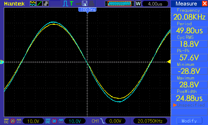
Picture 1. Output at 10db, 208W RMS power on 1.7ohm. The yellow waveform is the output of the amp, the blue one the voltage on Pin14 (output) of TDA7293.
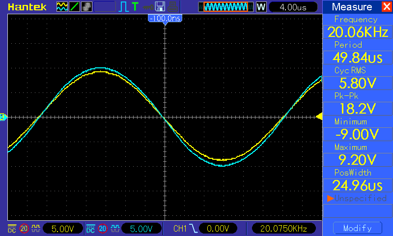
Picture 2. Output at 0db, 19.7W RMS power on 1.7ohm. The yellow waveform is the output of the amp, the blue one the voltage on Pin14 (output) of TDA7293.
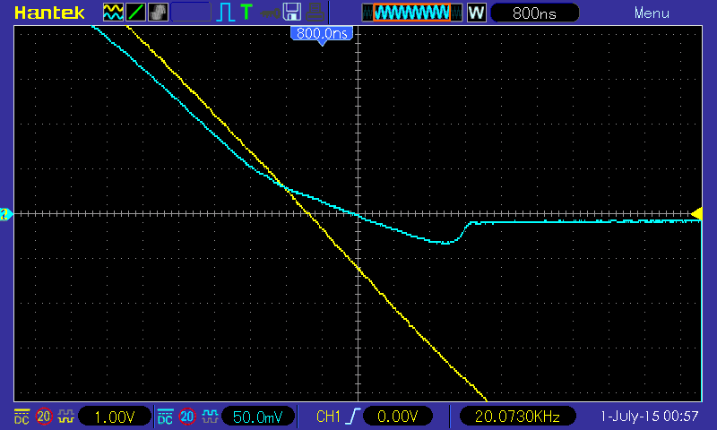
Picture 3. Zero crossing zoom at 0db, 19.7W RMS power on 1.7ohm. The yellow waveform is the output of the amp, the blue one the voltage on 0.1ohm resistor.
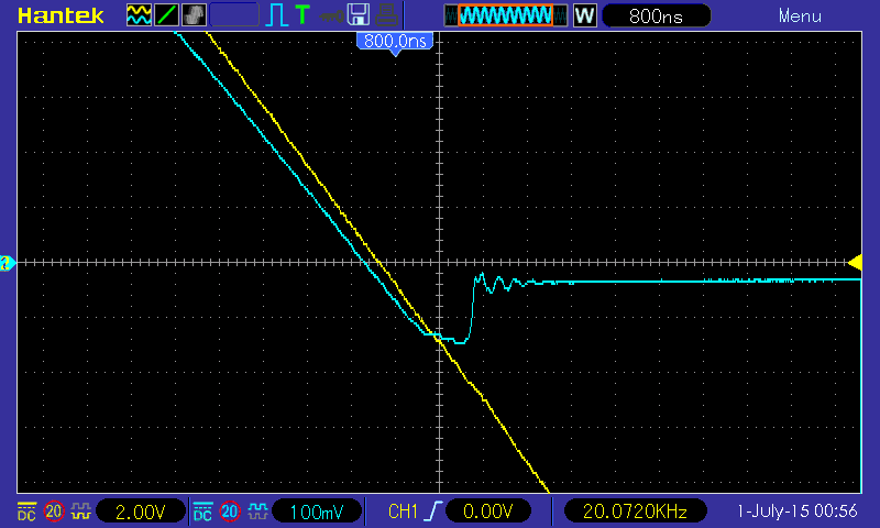
Picture 4. Zero crossing zoom at 10db, 208W RMS power on 1.7ohm. The yellow waveform is the output of the amp, the blue one the voltage on 0.1ohm resistor.
Waveforms in 2SC5200 & 2SA1943 emitters versus output:
These waweforms shows how positive stage (MJE15030 + 2SC5200) and negative stage (MJE15031 + 2SA1943) contribute to the output of the enhanced amplifier.
Blue waweform is the voltage on the emitter of 2SA5200, yellow waweform is the voltage on the emitter of 2SA1943 and the pink waweform is the sum of the previous two signals made by oscilloscope.
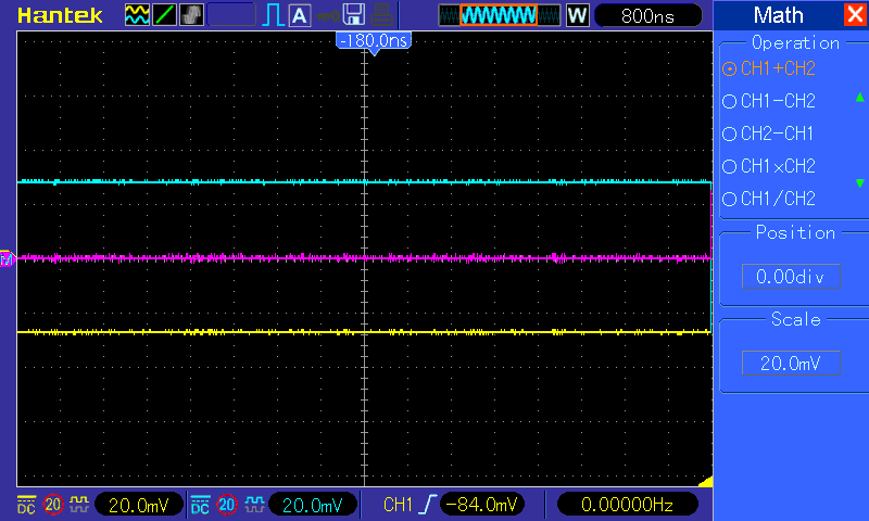
Picture 5. Voltage in absence of signal. As you can see voltage is about 25mV, which means the current through class AB stage formed by MJE15030/MJE15031 is about 250mA in absence of signal. This current can be lowered by using SF18 diodes instead of 1N4007. More current in absence of signal overheats the transistors. I don't advise more than 300mA nor less than 0.5mA.
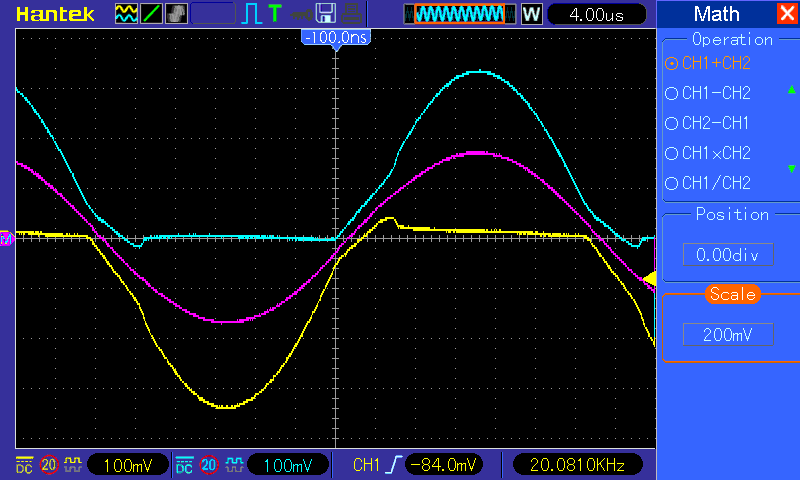
Picture 6. Voltage at 0dB signal. Pink waveform is the sum made by the oscilloscope of the two emitter signals and shows the current through load. You can see at zero crossover that positive and negative stages have simultaneous contribution due to the class AB behavior of the circuit, then at peak power every stage takes full contribution on it's polarity and the other rests near 0 voltage.
Contribution of every transistor stage of the enhanced amplifier to the power delivered:
Three stages contribute to the power delivered by this amplifier on load.
-First one and the leadig stage is TDA7293 itself. It contributes in two ways, by driving the two transistor stages and by injecting power directly to the output through 5.1ohm resistor.
-Second contributor is the AB class stage of MJE transistors, which drive the load at low and medium power
-Third contributor is the 2SC, 2SA power transistors, which deliver the bulk of power
From the following measurments the contribution of each stage can be seen and computed. Signals are taken across 0.1ohm resistor(reversed) and 0.47ohm resistor of the positive stage (negative stage behaviour is symetrical). The corrent through 0.47ohm gives the contribution of AB stage and the current through 0.1resistor gives the sum of contributions of AB and 2SA, 2SC stages.
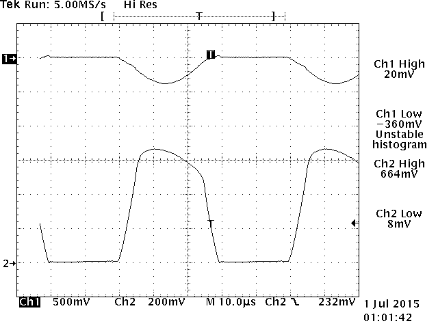
Picture 7. At 0dB signal. As you can see at this power MJE15030 drives 1.41A (0,664V/0.47ohm). The total peak current through both transistors is 0.36V/0.1ohm = 3.6A
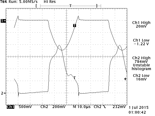
Picture 8. At 10dB signal. As you can see at this power MJE15030 drives 1.66A (0,784V/0.47ohm). The total peak current through both transistors is 1.22V/0.1ohm = 12.2A. (Voltage on 0.1ohm don't show the contribution of TDA to the total current delivered to load).
Contribution of TDA7293 to the output power of the enhanced amplifier:
I can compute now the contribution of TDA at the maximum power delivered on load.
The contribution of TDA consist in the current needed to feed the bases of final transistors plus the current delivered through the 5.1ohm resistor (the current through the 2.4Kohm bias resistors is negligible).
Fortunately using my measurements posted here, we know the current through the transistor stage, which is 12.2A (1.22V/0.1ohm). Datasheet states that 2SC5200 has a Hfe=10 at this current, so the base current needs to be 12.2/10=1.22A. (This is the worst scenario because a part of total current current, 0.78V/0.47ohm=1.66A is given by MJE15030 which has Hfe=20 at 1.66A).
Remeber that I measured the voltage of power supply under full load which was of+/-32V.
To be on no clip zone the exit of TDA was at 32-1=31V (which can be seen on picture 1 blue wawe).
The rms voltage on output was sqrt(P*R)=sqrt(208*1.7)=18.8Vrms (seen in same picture, yellow wawe).
The peak voltage on exit 18.2*sqrt(2)=26.6V. The current through 5.1ohm resistor is (31-26.6)/5.1=0.86A. Total current furnished by TDA at wawe peak is 0.86+1.22=2.08A.
Power delivered on peak by TDA is 2.08*31=64.48W. Because at lower currents Hfe of the final transistors is much greater, the contribution of TDA becomes lower during the rest of sine wawe period. So an overestimation of its contribution in terms of Wrms is 64.48/2=32.24Wrms.
It is a contribution overestimated and is about 15% of the total maximum power delivered on load.
At this power the total distortion of TDA7293 is given by producer at less than 0.05%, in fact due to overestimation of power, it is around 0.02% (Distortion vs Output Power of ST datasheet).
Test conclusion:
As tested the enhanced amp is able to continously deliver 208Wrms into 1.7ohm at high fidelity. (I measured FFT of the input and output signal at full power and they are absolutely similar).
In my experiment power was limited by the poor transformer. Using a good transformer (more than 400VA) able to deliver 32 - 34 Vac at least 308Wrms can be delivered on 1.7ohm load. That means 616Wrms on 3.5ohm on a bridged configuration, which is quite impressive!


